PROCESS SUMMARY
While FB and MH systems both accomplish thermal oxidation of sewage sludge/biosolids, there are several key process differences between these technologies, and each is described in the sections that follow.
Fluid Bed Technology
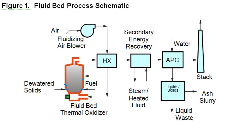
The FB thermal oxidizer is a vertical refractory-lined steel cylinder consisting of a windbox section at the bottom of the furnace into which combustion air is introduced, a bed section just above the windbox where the solids are fluidized along with the bed material (sand), and a freeboard section above the bed zone where combustion is completed. The windbox and fluidized bed section are separated by a refractory arch, metal plate or metal air distribution piping. The windbox type designation is determined by the temperature of the combustion air as it is introduced into the bed zone, with less than 200oF being classified as a cold windbox, 600oF to 900oF being classified as a warm windbox, and above 1,000oF being considered a hot windbox. The nozzles used to distribute air into the bed from the windbox below are called tuyeres.
Solids and auxiliary fuel are typically injected directly into the bed, though some FB units have over-bed solids feed. Combustion begins in the bed and completes in the freeboard, with the burning solids and exhaust gas moving co-currently through the furnace. Exhaust gas (including ash) exits the FB furnace at the top of the freeboard zone and then passes through energy recovery facilities (if included in the system design) before it is treated in air pollution control equipment. The most common form of energy recovery in a FB system is a combustion air preheater, which is typically a shell and tube heat exchanger used to preheat fluidizing air/combustion air to the desired process temperature. Downstream of the air preheater, other supplemental energy recovery devices have sometimes been installed, such as waste heat recovery boilers, thermal fluid heaters, exhaust gas re-heaters or water heaters. Ash is commonly removed in a slurry form via the wet scrubbing system, although some designs have a dry ash removal system upstream of the wet scrubbers, such as a cyclone, multiclone or baghouse. Dry ash systems facilitate beneficial reuse of ash, for example as an admixture in construction materials applications or as a fertilizer amendment based on increased phosphorus and potassium content in the ash.
FB systems typically operate at 40-50% excess air and exhaust temperatures of from 1,450oF to 1,600oF. Due to the relatively low excess air levels that can be achieved with FB systems, coupled with their ability to utilize very high (up to 1,200oF) air preheat temperatures, FB systems can operate without auxiliary fuel (or nearly so) with 26-30% feed solids content. This is referred to as autogenous combustion. Normal residence time of a solid fuel particle within an FB system ranges from 1 to 5 minutes and the gas detention time at high temperature ranges from 5 to 8 seconds, which is responsible for the very low levels of Carbon Monoxide (CO) and Total Hydrocarbons (THC) in FB exhaust. FB systems all have a fluidizing air blower and some systems also have an induced draft (ID) fan. The latter are referred to as “push-pull” systems and normally operate at a negative pressure from the freeboard zone of the furnace through to the inlet of the IF fan. In the absence of an ID fan, the system is referred to as a “push” system and operates under positive pressure through to the final exhaust stack.
Early FB systems used almost identical designs and process configurations. Over the past 25 years, a number of process innovations and modifications have been made to the traditional FB system designs aimed at improving performance, fuel flexibility or reliability; increasing system capacity; meeting stricter emissions limits; and/or recovering energy or byproducts for recycling. Some key FB process modifications have included:
- The addition of “overfire” air to the freeboard zone, providing increased gas-phase mixing in the freeboard and enabling the air to be staged between the bed and freeboard to match heat release and reduce auxiliary fuel input.
- Providing ductwork and control valves to enable a portion of the combustion air to bypass the main air preheater, thus providing increased operating flexibility and control of combustion air preheat temperature.
- Use of dry ash collection systems, thus enabling the ash to be recovered for beneficial reuse and/or reducing the ash load on the wet scrubber. Biosolids characteristics are changing, as enhanced nutrient removal systems are applied. For example, biological phosphorus removal increases the biosolids phosphorus and potassium contents, much of which stay with the ash and impart additional value as a slow-release fertilizer.
- Feeding of sludge/biosolids above the bed, rather than injecting it directly into the bed zone. Whatever the feed system, it should be properly maintained and operated as designed.
- Use of natural gas instead of fuel oil as the main operating auxiliary fuel used to control bed temperature. Gas is often used for overbed burners to start up the process, but has been injected directly into the bed as auxiliary fuel in some cases.
- Use of superficial velocities within the bed zone higher than the traditional three (3) feet per second benchmark used in the earliest FB designs and continued for many years. This can enable the system to process more capacity in the same size bed. Over time, though, bed chemical composition and particle size distribution changes, which can affect fluidizing velocity and fluidizing air requirements, so flexibility should be required to permit fluidizing air flow adjustments over time. Modern Olivine bed materials wear differently than their predecessor silica sand medias and the ash from modern nutrient removal biomasses tends to agglomerate more and remain in the bed.
- Use of extended freeboard height to provide increased gas phase contact time and minimize bed material losses resulting from entrainment of bed materials in high-velocity localized gas jets erupting from the surface of the bed.
- Provision of means for removing oversized inert material from the bed zone while the FB system is in operation. This enables the operator to remove bed material quickly while it is hot, to maximize uptime and facilitate management of bed composition via removal of used media and addition of makeup media, both while the system is operating.
- Introduction of secondary energy recovery to produce steam or heated thermal fluid and use of the recovered energy for power generation, building heat or thermal dewatering (scalping) of the feed to achieve nearly autogenous combustion.
- The application of a variety of improved air pollution control devices, such as multiple venturi wet scrubbers, wet electrostatic precipitators, baghouses, and secondary (post-combustion) systems, such as carbon adsorption systems for Mercury (Hg) removal or SCR/SNCR systems for reducing NOx emissions.
- The addition of eutectic modifier chemicals such as limestone, lime, and kaolin clay, to raise the ash softening and melting temperatures of ash from enhanced nutrient removal biomasses. Limestone or lime also serves to neutralize acid gases related to the sulfur in biomass and can potentially mitigate corrosion and/or erosion. Controlling SO3 is also proven to improve carbon adsorption where carbon is applied for mercury and/or dioxin/furan removal.
A schematic of a typical modern fluid bed system is presented in Figure 1.
Multiple Hearth Technology
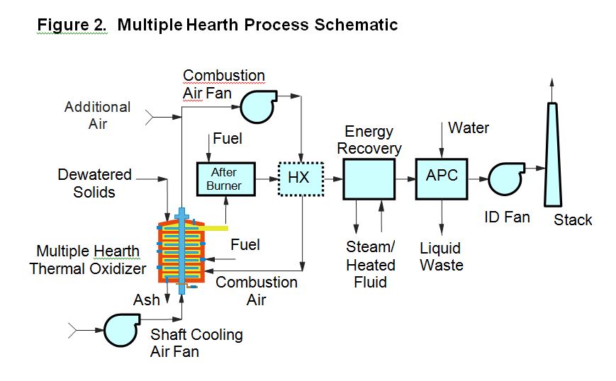
The MH thermal oxidizer consists of a vertical refractory-lined cylinder with a series of horizontal refractory brick hearths, stacked one atop the other. Hearths either have a series of drop-holes around the periphery or a single large central drop-hole for material to pass downward through the furnace from one hearth to another. A rotating center shaft extends the height of the unit and supports the rabble arms above each hearth. Each rabble arm is equipped with teeth or plows which rake the solids across the hearth in a pattern to facilitate drying and burning. Solids are typically fed into the top hearth and are plowed or “rabbled” from one hearth to the next. Generally, solids are plowed between a single inner drop-hole (“in hearth”) and multiple outer dropholes (“out hearth”) on successive hearths. Solids feed is generally to an “in hearth” and there are typically an even number of hearths. Sometimes the top hearth serves as an afterburner, or “zero-hearth”. In that case, the solids feed passes directly through to the second hearth to begin the rabbling process. Most of the ash is discharged from the bottom hearth and may be handled in dry form or slurried and handled in wet form. Combustion air is typically introduced to the lower hearths and flows upward, countercurrent to the solids.
From a process perspective, the MH is separated into three zones. The top hearths comprise the drying zone where water is evaporated. The middle hearths comprise the combustion zone where the volatile solids are oxidized and the fixed carbon combustion is completed. The bottom hearths comprise the cooling zone where the ash is cooled by incoming combustion air. Some of the hearths in the drying zone and the combustion zone are equipped with auxiliary fuel-fired burners that are used selectively to provide additional thermal energy where required within the system.
In operation, the hottest hearth in the combustion zone operates from 1,400ºF to 1,600ºF and its location may move up or down from hearth to hearth within the furnace in response to changes in feed rate or characteristics. Combustion air flow is adjusted to keep the hottest hearth below 1,600oF and normally falls in the range of 75-125% excess air. Because of the configuration of MH systems, it is usually impractical to use any significant level of air preheat, as this would require still higher air flow rates to keep the hottest hearth cool. Often, the warm shaft cooling air is returned to the system combustion air fan or directly to the lower hearths. Sometimes, a heat exchanger is used to provide low levels of combustion air preheat, but this is rare in a traditional MH system. As the products of combustion move up through the drying zone, heat is transferred to the solids and the evaporation of water from the feed causes these gases to cool, resulting in exhaust gas temperatures at the top of the furnace often in the range of 900oF to 1,200oF, depending on feed solids content and the amount of auxiliary fuel added via the burners in the drying zone. These temperatures are high enough to volatilize some of the organic content in the feed, but not high enough to complete combustion of the volatilized compounds, which translates to higher emission levels of CO and THC and the potential for odors in the exhaust stack. As a result, MH furnaces are often equipped with afterburners, either as a “zero” hearth (above the feed hearth) or an external afterburner chamber located downstream of the furnace exhaust duct. Ideally, afterburner temperatures would be at least 1,400oF in order to minimize these emissions; however, many systems operate as low as 1,200oF and achieve acceptable performance with lower auxiliary fuel usage. The normal residence time of a solids particle in a MH system is 40 to 60 minutes. Energy recovery systems have sometimes been used with MH systems, most commonly to produce steam for power generation, plant heating or to meet other plant thermal loads.
As with FB systems, a number of process innovations and modifications have been made to the traditional MH designs over the past few decades. These innovations have typically been directed at making the process more efficient (reducing fuel consumption); increasing furnace exhaust gas temperature; meeting stricter emissions limits; and/or recovering energy of byproducts for recycling. Some key MH improvements have included:
- The addition of mixing jets to each hearth to improve gas mixing and promote heat transfer through the system.
- The addition of piping and valves to enable controlled introduction of combustion air on individual hearths, rather than adding it all at the bottom of the furnace.
- The development of air-tight furnace designs to facilitate operation at reduced excess air levels (~40 to 60%) or in starved air combustion mode.
- The development of the process modification involving flue gas recirculation to achieve higher exhaust temperatures and improved emissions without adding auxiliary fuel.
- The development of the RHOX process modification whereby an afterburner was added following the wet scrubber using a regenerative thermal oxidizer to provide a more efficient means for reducing emissions of CO and THC.
- Introduction of secondary energy recovery to produce steam or heated thermal fluids and use of the recovered energy for power generation, building heat or other plant/process thermal loads.
- The application of a variety of improved air pollution control devices, such as multiple venturi wet scrubbers, wet electrostatic precipitators, and secondary (post-combustion) systems such as carbon adsorption systems for Mercury (Hg) removal or SCR/SNCR systems for reducing NOx emissions.
A schematic of a typical modern multiple hearth system is presented as Figure 2.